Scribes: Yin Lok Ho, Wilson Sun, Salim Youssefzadeh
“Pushing down” in one area would lead to “rising up” in another area. Typically, improvements in one aspect of design will inevitably lead to some tradeoff in another aspect of the design. For example, improving speed in a program often leads to bloating the program.
“No such thing as free lunch”
Example: Sorting in RAM
Assume memory of size 10GB that includes many records of 1KB each.
This gives a total of 10 million individual records. Some sorting methods are quicksort and heapsort. These sorts, however, operate on the memory directly. These operations become quite slow since they are copying copies of 1KB records O(NlogN) times where N is huge (10 million).
An alternate sorting algorithm would be bucketsort. In bucketsort, instead of manipulating the records themselves, we create an array of pointers that point to each record. We then perform the sorting on the pointer array instead. Since each pointer is only 8 bytes (versus the 1KB records), the cost of copying 10 million pointers is much smaller than that of copying 10 million records.
This method is actually 1024 bytes (1KB) / 8 bytes = 128 times faster in terms of copying overhead.
However, what are the tradeoffs?
In bucketsort, we had to create the array of 10 million pointers. Although each pointer is only 8 bytes, an array of 10 million still becomes quite significant. Since we already established to total cost of the pointers array is 1/128 of that of the records array, the cost becomes a factor of (1 + 1/128) larger than the records array alone.
This tradeoff, however, is definitely worthy since we are trading a small bloating of space for an improvement of a factor of 128 in speed.
Assume a world far, far away, where users do not trust software.
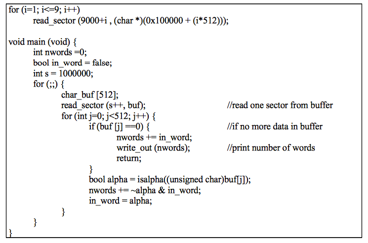
A professor, who is on the verge of finalizing her groundbreaking thesis, hired you to write a program that would count the total number of words in her document due to the length constraints imposed by the International Groundbreaking Thesis Acknowledgement Board (IGTAB). However, the professor does not trust any software unless it is written by you. This means that she wants nothing but YOUR program to run on her computer. No Windows. No Linux. No OS X. No Snow Leopard. No Jaguar. No Tiger. No Tigger. No Kitty Cat. No nonsense.
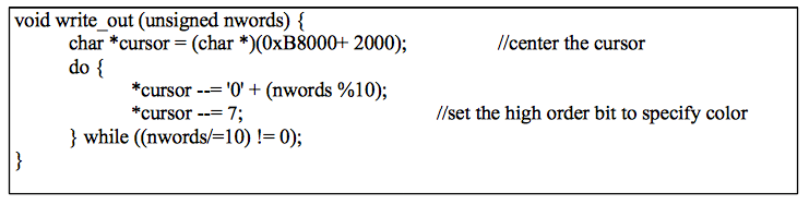
The professor also wants an extremely simplified UI that would allow her to simply plug in the computer and be able to read the word count directly from the monitor.
Aside: Typically in any project, this is a good place to do some “requirements gathering” so that we know exactly what we are trying to build.
Here are some requirements and specifications you gathered:
· The document is pure ASCII and is stored on an HDD inside the computer.
· Computer should only execute code you write.
· Program should be “plenty fast.”
· Storage on disk is up to you.
· The computer is a Dell PC, x86 architecture, 1GB RAM, Core 2 Processor @ 2GHz, 1TB HDD, and is connected to a monitor, which is its sole I/O device.
· A word is defined as anything that matches the regexp [A-Za-z]+. Anything else is ignored.
· You have to read through the machine code to verify correctness and trustworthiness.
· Disk drive runs at 7200rpm, with a transfer rate of 500 Mb/sec, average rotational latency of 4+1/6 ms and an average seeking time of 10ms.
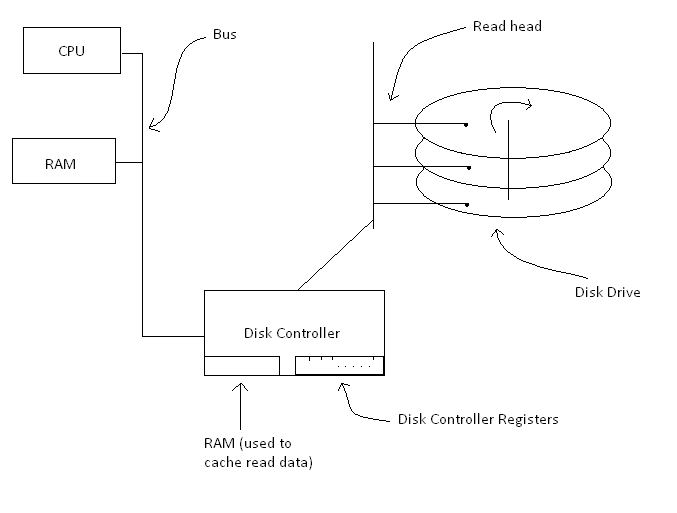
A View of the System in Question
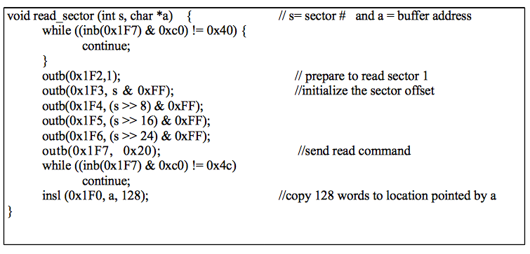
In the disk controller, there are several “disk controller registers” that allows communication between the CPU and the disk drive. These registers are addressable by the CPU. The register mapped to 0x1F7 is known as the status register. When the register reads 01, representing the ready state, the CPU could communicate with the disk drive.
The CPU requests for data by storing the number of sectors it wants to read into disk controller register 0x1F2. A sector is simply a unit of disk space (512 bytes). Each sector on the disk drive is indexed in a similar fashion as arrays. The CPU then stores a sector offset into registers 0x1F3 through 0x1F6. A sector offset is simply the index number of the first sector it wants to be read. Note that each register could only store 8 bytes. Thus, since we can only store the offset into 4 registers, the longest offset could only be 32 bytes long.
Aside: Note that this limit of 32 bits means that we could only address 232 sectors * 512 bytes/sector = 2TB of disk space. This is the reason that the industry is currently (April 2010) working on increasing the number of bytes each sector could store.
Once the number of bits and the offset is stored, the CPU then stores the READ command into register 0x1F7 and wait for the disk to go in the READY state. Once the disk is in said state, the CPU will obtain results of the read as data out of register 0x1F0 and store them into RAM. At this point, you might wander what would happen if the required data would not fit in a single register at once. God forbid that we want more than 8 bytes worth of data. This actually does not present a problem since the data is obtained in a streaming fashion that allows for continuous data flow from the disk to the CPU and then to RAM.
Bootstrapping
When the computer is turned on, it attempts to “boot” by running some built-in program. This program is often stored in some variation of an elastic read-only memory that is sectioned off on the computer’s RAM. Inside this section of the memory, values do not change and, unlike their counterparts in RAM, they stay valid inside memory even after the computer is powered off and then back on. The built-in program stored inside this section of memory is called the BIOS, short for Basic Input/Output System, and is used to initialize the booting sequence of the computer.
What happens in the computer as it starts up?
Initial state of CPU:
· RAM = All 0s
· CPU = All registers 0s?
o Is Program Counter also 0? (instruction at 0x0 = ? which means the computer halts?)
· Program Counter initially points to a part of the RAM that contains the BIOS stored in ROM
o EEPROM: Electrically Erasable Programmable ROM
o From point of view of people who write BIOS, OS is simply a subroutine
o BIOS is also called firmware
RAM:
|
0’s |
ROM/EEPROM (BIOS) |
Bios – What does it do (traditionally)
1. Test the system
· Checks CPU, RAM, memory pattern etc.
· Note: Server tests tend to be more comprehensive than those for consumer computers. Therefore servers take much longer to boot.
2. Look for devices / Probe for devices
· Loads and stores to device registers
· Tries to read from first sector of every device to check if device is bootable/a boot program exists.
· Components of a bootable device’s first sector:
Master Boot Record (MBR) – first sector of device, x86 machine code, OS independent
Partition Table – status of partition (bootable?), type, start sector number, size of partition (16 bytes total for each partition)
Signature – 0x55, 0xAA (or equivalent to 0xAA55 due to little endian)
|
MBR (446 Bytes) |
Partition Tables (64 Bytes, 4 partitions) |
Signature (2 Bytes) |
512 Bytes total
A note on little endian vs big endian:
If 2 pieces of software disagree on the size of a piece of data (32bit vs 64bit) but both agree on address, little endian will yield the same result for both software providing the data is not too big. (Consequently professor Eggert says that little endian is better)
Big endian: ^[0][0][1][2]
Little endian: [0][0][1][2]^
^ = address of the piece of data
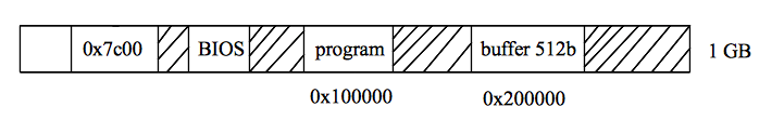
· Bios copies entire sector into RAM at address 0x7C00
· Typical MBR operation:
(*programs rarely fit into 446 bits therefore MBR boots other things instead)
i. Scan partition table
ii. Find bootable partition
iii. Load volume boot record (VBR) into RAM
1. Usually designed for OS on the partition
iv. Jump to it => VBR takes over (for the case of our application, copies our application)
v. Example: Linux
MBR => VBR => GRUB => OS
· Note that at each stage, booting program is the OS (can choose to shut down the computer etc)
Memory Layout:
Disk Layout:

OS Code:
VBR code:
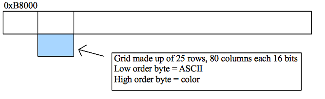
Memory mapped I/O:
Certain addresses map directly to I/O devices. Each read or write to this address, then, is an interaction with the I/O device. For example, the following address is mapped to the monitor: