CS 111 - Spring 2010Lecture 11: File System DesignWritten by: David Chen, Steven Liu, Flint LuuLecture TopicsFlash vs. DiskIn the last lecture, Professor Eggert briefly mentioned flash drive technology and the differences between flash and regular disk drives. A Flash drive, or SSD (Solid State Drive), has no moving parts and generally has lower latency for read/write operations in comparison to conventional disk drives. Random access is fast because there are no seek times involved, however blocks must be erased before writing. Flash technology is still very young and it is constantly evolving. Below is a table comparing 2 different variations of a particular model of SSD (the Corsair Nova Series SSD's).
Also of interest is a comparison to a disk drive of similar specs. The following are the specs for a Seagate hard drive.
As we can see the hard drive beats the SSD's in read/write speeds but in general most numbers/figures thrown out by the manufacturers are bogus and don't correspond to actual operation speeds. In general, flash drives will beat out hard drives in write/read speeds. Flash technology seems good and advantageous, but there are some drawbacks:
As flash technology progresses and becomes more mainstream, the cost will probably decrease just like it did for harddrives. For the problem of wearing out, a lot of flash drives nowadays use a technique called "wear-leveling" to prolong drive life. "Wear-leveling" simply means writes are directed to the least-written blocks in the device, and thus all the blocks age more uniformly. This technique can be implemented in the OS or the device itself (firmware). However "wear-leveling" has its own problem, as the logic overhead needed to implement it incurs a performance loss on writes. File System DesignA File system is defined as an on-disk data structure that represents a set of files that are organized by a tree-like directory hierarchy. RT-11 File System
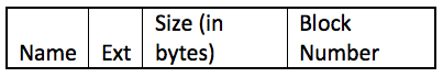
Here is an example of a file system that Eggert wrote (it resembles a real-world file system):
The design of this File System seems simple and problematic but in fact is very similar to the RT-11 File system that was used in the 1970s. What are problems with this?
What are the advantages (if any)?
FAT File SystemFAT (File Allocation Table) File SystemBeginning in the 1980s, the FAT file system is another computer file system architecture we went over in class which is found in many memory devices now such as memory cards. The memory lay out is shown in the figure below (with the description below that).
For the FAT file system, there can be regular files and directories.
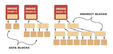
Berkeley Fast File System (Unix-like filesystem)Developed by a Berkeley graduate student, this file system has been used by many Unix and Unix-like operating system. There have been minor variants to this version but for the most part, the BFFS has a solid foundation. The disk space structure is divided into the following: Boot Sector: Information on disk booting and loading up the OS. The idea of inodes introduces a few new implementations and the idea of holes. The reason for inodes is we want to find files fast (thus a pointer-type hierarchy) and we want those files to hold a lot of data (data blocks with pointers to more data). Inodes (Index nodes)Index nodes are fixed-size file descriptors that hold a file's metadata such as size, permissions, owner, links, and timestamps. A single inode represents either a file or directory, but the interesting thing is they DO NOT hold file/directory names. Read under links for more details. Each inode holds at least a certain number of direct block pointers, a few indirect block pointers, and possibly even doubly indirect block pointers. These pointers point to the actual data that the file stores and depending on the type of UNIX file system, block sizes may vary. Assuming each block is 1024 (1 KB) and pointers are 4 bytes, then each data block can hold 256 pointers. That means an indirect block can hold up to 256*1024 = 260 KB and that doubly indirect blocks can hold up to 67 KB. This doesn't seem like much but I'm assuming quite a low block size count. The illustration below provides a simple look at inode hierarchy:
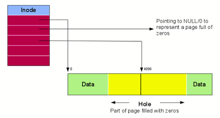
LinksEarlier, we mentioned that inodes do not have file/directory names, or to put it more clearly, files and directories in linux are not explicitly identified by their names. Each file has its own inode number and you can use the ls command in linux to find that number and more inode information. Because of identification by inode number, unique files can have the same name. There are two types of links. The first is a symbolic link, also known as a soft link. Think of this as the shortcuts you create to files when using Windows. If you delete the original file, you can no longer use the symbolic link because it is now broken or dangling. In other words, symbolic links are just pointers to the actual files and its contents are the filename it is pointing to. Note: It is possible for loops to occur if symbolic links point to each other. The second type of link is a hard link. Each inode has a link count and it refers to the number of hard links that refer to a specific file. A hard link not only points to the original inode but also possesses its same contents by cloning them. As long as the link count is not 0, a file will exist. Otherwise, the file's data block will finally be deallocated. HolesThe main issue with the inode hierarchy is the existence of holes. In BFFS, file allocation is contiguous and gets rid of the issue of external fragmentation. Unfortunately, in this system, we have to replace deallocated addresses with 0's and that creates holes. When we read from these, we get 0's and when we write, these absent blocks get allocated and hold data. But once those are allocated, they become new holes as well. Holes are quite small and insignificant but they do still take away some memory.
|
|||||||||||||||||||||